Colab
Concept Design
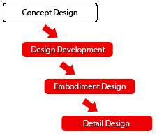 The first stage involves generating ideas based on form, function, features, specifications, benchmarking and economic justification.
Design Development
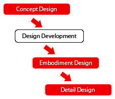 The second stage involves selecting, developing and evaluating suitable concepts based on set specifications.
Embodiment Design
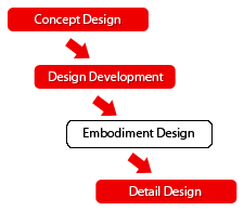 The third stage creates a fixed layout by selecting the most desirable configuration, evaluating against technical and economic criteria.
Detail Design
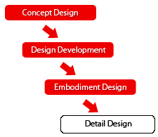 The fourth stage realises the physical product through specification of details such as materials, dimensions, size, assembly, with final testing before production.
Design Intent
Identifies the design concept and product purpose including aesthetics, safety and usability.
Form & Detail
Identifies the product?s appearance with respect to form, in terms of structure, shape, proportion and size.
Visual Character
Identifies the product personality or character that a product conveys to the user, usually through the external form, choice of materials, texture and finishing.
Usability & Operation
Identifies how well the product is capable of being used, including functional effectiveness, ergonomics and operational efficiency.
Scenario of Use
Identifies how a product would be used in a projected sequence of events and may include relationships between the user, environment and product.
Single View
Comprises of isometric, trimetric, perspective, oblique and axonometric projections in the form of sketches or drawings.
Multi View
Diagrammatic views through first-angle or third-angle projections in which the form is flattened out with plan views, front elevations and end elevations.
Areas of Concern
Identifies issues concerning the overall design that include safety, usability, ergonomics and production.
Finishing
Identifies the texture (external surface perceived through touch) and surface finish (coating applied to the product)
Colour
Identifies the visual attributes of the product's appearance in terms of hue, lightness and saturation
Dimensions
Generally comprise measurements for parts, including angles and tolerances with a specified unit of measurement.
Construction
Refers to the arrangement and composition of parts that when put together make the product.
Assembly
Describes the process whereby the manufactured parts are put together to make the completed product.
Components
Consists of connecting parts which when assembled from the overall working product and may be classified as electrical and mechanical components.
Mechanism
Involves the assembly of connected moving parts and its physical operation to perform a function.
Part & Section Profile Lines
Lines that delineate the form, section or area of a product and includes parting lines where two parts are assembled together or where moulding dies meet.
Exploded Views
Shows parts of a product separated by distance to display the components contained within the assembly.
Material
The substance from which the physical product part is made up.
Sketches
Idea Sketch
 Shows what design ideas look like as physical objects and are used at a personal level to externalise thoughts quickly. Also known as thumbnail, thinking or napkin sketches.
Study Sketch
 Used to investigate appearance and the visual impact of ideas such as geometric proportion, configuration, scale, layout and mechanism.
Referential Sketch
 Used as a diary to record observations for future reference or as a mataphor.
Memory Sketch
 helps users recall thoughts and elements from previous work and usually includes notes and text annotations.
Coded Sketch
 Informal representations that categorise information, usually to show an underlying principle or scheme.
Information Sketch
 Allows stakeholders to understand the designer's intentions by explaining information clearly and to providea common graphical setting. Also known as explanatory or talking sketches.
Renderings
 Formal proposals of design concepts that involve the application of colour, tone and detail for realism. Also known as sketch renderings or first concepts.
Inspiration Sketch
 Form orientated sketches used to communicate the look or feel of a product by setting the tone of a design, brand or product range. Also known as emotional or inspiration sketches
Prescriptive Sketch
 Informal representations used to communicate design decisions and involves general technical information such as dimensions, material and finish. Also known as specification sketches.
Drawings
Concept Drawing
 Shows the finished product using precise line drawings. Also known as layout drawings.
Presentation Drawing
 Final drawings for clients and other stakeholders. They can be used for reference and may include exploded views with technical details.
Scenario & Storyboard
 Used to suggest user and product interaction, and to portray use in the context of artefacts, people and relationships.
Diagram
 Abstract representations of the underlying principles of an idea or represents relationships between objects. Also know as schematic or diagrammatic drawings.
Single-View Drawing
 Comprises of isometric, trimetric, perspective, oblique and axonometric projection drawings.
Multi-View Drawing
 Diagrammatic views through first-angle or third-angle projections in which the form is flattened out with plan views, front elevations and end elevations.
General Arr. Drawing
 Embodies the refined design but omits internal details. Used in the production of an appearance model with limited details. Also known as model making drawings.
Technical Drawing
 Represents the built object and covers every product detail for manufacture. Also known as engineering, production or construction drawings.
Technical Illustration
 Graphical illustrations to explain technical details and use conventions of engineering drawings incorporating signs and symbols within the illustration.
Models
3D Sketch Model
 Informal three dimensional block representations that represents the design idea. Also known as foam models, sketch models or 3D sketches.
Design Dev. Model
 Used to increase understanding of relationships between components, cavities, interfaces, structure and form.
Appearance Model
 Exact visual representations of the design proposal defining the product form and use, but do not contain working mechanisms. Also known as block, iconic or qualitative models.
Functional Concept Model
 Shows functionality and highlights important functional parameters including yield and performance factors.
Concept of Op. Model
 Helps communicate understanding of operational strategies and usage procedures relating to the product.
Production Concept Model
 Used to help assist the evaluation of production processes or manufacturing technologies for final production.
Assembly Concept Model
 Shows component relationships to provide confidence in assembly, cost and investment.
Service Concept Model
 Illustrates how the product is serviced and maintained, and may be in the form of exploded views to show the disassembly of parts with servicing information.
Prototypes
Appearance Prototype
 Highly detailed, full-sized models that combine functionality with product appearance.
Alpha Prototype
 The first construction of the sub-systems that have been individually proven and accepted. Fabricated using materials, design and layout that will be used for the actual product.
Beta Prototype
 The first full-scale and fully-functional prototypes constructed from the actual materials as in the final product.
Pre-Production Prototype
 Final prototypes used to perform production and assembly assessment using production tooling for small batches.
Experimental Prototype
 Physical prototypes used to perform or parameterize physical properties of the product. Also known as design-of-experiment prototypes.
System Prototype
 Combines the numerous components specified for the final product. Used to test and assess assembly, mechanism and performance.
Final Hardware Prototype
 Assists in the design and evaluation of product fabrication and assembly issues.
Tooling Prototype
 The physical tooling allows potential problems to be intercepted before any discrepancies in form or fit occur.
Off-Tool Component
 Components produced using the tooling and materials intended for the final product.
CoLab: a design tool to support education and collaboration for engineering designers and industrial designers during new product development